
- All
- Product Management
- News
- Introduction
- Enterprise outlets
- FAQ
- Enterprise Video
- Enterprise Atlas

Hotline 19928718048

Handheld Intelligent Tightening System Solution
Classification:
Solution
Solution
Author:
Source:
Release time:
2019-01-21
Visits:
1
Chapter One Overview
China's manufacturing industry has developed rapidly, with the manufacturing output value exceeding that of the United States in 2010, making China the largest manufacturing country. Currently, among more than 500 major industrial products, our country has over 220 types, ranking first in the world. Among this vast array of products, there must be a massive number of screws that need to be tightened. Driven by the entire manufacturing industry, a huge fastening market has been created. The fastening industry is developing towards automation and intelligence, but achieving industrial automation and intelligence is not an overnight process; it requires a long evolutionary process.
As the spirit of all things, humans possess intelligent minds and dexterous hands. In many fine processing scenarios, machines are still temporarily unable to replace human roles. However, humans are not machines; their work state is influenced by the environment and mood, making it a dynamically fluctuating quantity. Because of this, people often make small mistakes in their daily work.
In today's world, where industrial intelligence and unmanned fastening have not yet been achieved, and for a long time in the future, what can we use to ensure the quality of product fastening? To address this, Sensewee has launched a handheld intelligent tightening system that combines human and machine. By utilizing the intelligent automatic tightening system in conjunction with the clever human brain and dexterous hands, the best results can be achieved. The intelligent tightening system can not only automatically determine whether the fastening result is successful or failed but can also provide the type and reason for the failure when tightening fails.
Chapter Two Traditional Fastening Analysis
In large OEM factories, workers holding traditional electric screwdrivers to fasten screws on products is the most common scene.
The biggest advantage of traditional electric screwdrivers is their simplicity and low price; however, traditional electric screwdrivers also have many defects, such as high failure rates, short lifespans, and inability to precisely control torque and speed. Traditional fastening only yields a vague result, and both the tightening process and result cannot be digitized or standardized, relying solely on the experience and feel of the workers. Issues such as over-tightening, stripping, and missed screws often occur. Once a problem arises, it is impossible to trace and investigate; this poses a significant quality risk for the product. To ensure the quality of product fastening, it relies on the workers' sense of responsibility and the quality inspection's extensive checks on products. Neither of these is a reliable method. Both workers and quality inspectors are human and are easily influenced by external environments; workers may miss screws, and inspectors may overlook checks.
Chapter Three Handheld Intelligent Tightening System Solution
Based on the current situation and demands of the intelligent era and the fastening industry, our company proposes a handheld intelligent tightening system solution. This solution includes scanning devices, intelligent electric screwdrivers, industrial tablet computers, and software systems.
To address the need for data management, our project team has decided to use a stable industrial tablet computer combined with a scanning gun, equipped with our intelligent electric screwdriver, to form an intelligent tightening system.
3.1 Scanning Gun
Supports one-dimensional and two-dimensional code scanning, with an error rate of less than 1:5000000, 640*480 CMOS, recognition accuracy >= 5mil.
Supports manual button scanning and automatic induction scanning, and supports RS232 communication. The data collected by scanning is transmitted to the industrial tablet computer via the serial port.
3.2 Industrial Tablet Computer
Win7 operating system, 128G solid-state drive, 2G memory, 2*RS232 2*USB2.0, 2*USB3.0.
3.3 Intelligent Electric Screwdriver
High precision torque control, with torque accuracy deviation maintained within 5%;
Supports task parameter settings for 8 different types of screws, with each task parameter divided into 5 tightening steps;
Supports various IO outputs and alarm outputs; for example, over-tightening, stripping;
Anti-static design;
Tightening result record output;
3.4 Infrared Sensor
Senses whether the product is in place and whether it has been removed;
3.5 Management Software System
The management software system serves as the center for data collection and processing; it needs to operate stably for a long time, generating a large amount of work data daily, so the system must have certain self-management and maintenance functions to prevent the burden of a large amount of work records on the system.
(1) Overview of the System Software Main Interface
The interface is mainly divided into four areas, specifically:
① Upper left corner function menu;
② Upper right corner function tab page;
③ Central function module display area;
④ Bottom status bar, displaying communication, task details, alarm status;
(2) Communication Settings
The system's default device number is 1, the default communication baud rate is 115200, and the communication port number is automatically recognized; the software usually connects automatically.
[Scan Search] This function can find devices that are normally connected and online.
(3) Device Information
After a successful connection, the model of the handheld intelligent controller and the version information of the management software will pop up.

(4) Task Planning
Task planning is an important function in the system, and the rationality of parameter settings determines the work efficiency of the intelligent tightening system and the success rate of fastening.
1.[Load Task] Import previously saved task files from the hard disk;
2.[Save As] Save task parameters as hard disk files;
3.[PC<
5.[Save] Save the current task parameters in the controller;
[Note: When saving parameters, do not let the electric screwdriver stay on the tightened screw; wait 5 seconds after saving before proceeding with subsequent operations.]
6.[Restore Factory Settings] Restore the default task parameters of the controller to factory settings;
[Note: When restoring factory settings, do not let the electric screwdriver stay on the tightened screw; wait 5 seconds after restoring factory settings before proceeding with subsequent operations.]
7. Task Selection: Choose the task number to set from 00 to 15; the number of tasks displayed is the maximum number of tasks supported by this controller.
8. Task Step Settings: Set the planning and order for each task.
[Tightening] Currently supports STEP0 to STEP4, a total of 5 STEP travel plans, where each STEP can set the number of tightening cycles and tightening speed for the screws; if the set cycles are greater than 0, that STEP is valid; if the set cycles are equal to 0, it is an invalid STEP.
The program will automatically skip invalid STEP steps and then execute the subsequent valid STEP steps.
[Loosening] Set a maximum of 2 steps, with parameter settings similar to the tightening method;.
[Free] Set the rotation speed and direction of the electric screwdriver, with start and stop controlled by command input or disconnection;.
[Additional Items] Choose the torque unit to use: mN.m/0.01Kg.m^2 two options;.
Output effective time coupling status: ON / OFF, default is OFF, output low level is effective;.
9. Task Parameter Settings: Set the relevant parameters for each task.
Tightening Mode: Supports 2 modes, namely
0--Automatic mode, speed range 30-1200rpm;.
2--High-speed mode (suitable for self-tapping screws), speed range 30-1800rpm;.
Tightening rotation direction: (with the bit head facing up as a reference) 0—CW (clockwise); 1—CWW (counterclockwise);.
Target Torque: Set the size of the final target torque value for locking screws;.
Torque Holding Time: The time to maintain the target torque after reaching the target value;.
Torque Compensation Value: When there is a fixed deviation between the set target torque and the actual torque, set this parameter to add or subtract a value; when setting this parameter, first set a slightly larger value (e.g., 10 or -10), then observe the feedback effect from the torque meter for further fine-tuning.
Standby Adjustment Time: The time to wait after the electric screwdriver stops running before switching the bit head to free state.
Floating Height Slip Detection: 0=off; 1=on. (Default off, for debugging; it is recommended to turn on during actual use)
After enabling this function, the parameters "–Floating Height Definition Cycles" and "+Slip Definition Cycles" will be effective;
If not enabled, the tightening results will only have three states: OK, NG, and incomplete; it will not check for floating height and slip.
–Floating Height Definition Cycles: Used for setting the floating height judgment value;.
Movement cycles < Set cycles - Floating height definition cycles If the torque has reached the target torque, it will report floating height.
+Slip Definition Cycles: Used for slip judgment value setting;.
Movement cycles = Set cycles + Slip definition cycles If the torque has not reached the target torque, it will report slip.
Whether to enable the entry function: temporarily not supported.
Initial detection quantity: temporarily not supported.
Whether to enable the tapping function: 0=off; 1=on.
When performing self-tapping screws, during the initial stage of locking screws, there may be a situation where the required torque exceeds the target torque value; at this time, it is recommended to enable the tapping function and use the torque values in STEP-n for segmented torque settings and "tapping exempt torque cycles".
Initial tapping torque: temporarily not supported.
Tapping exempt torque cycles: After enabling the tapping function, multi-segment STEP travel and speed planning can be set;.
Tapping exempt torque cycles = the total number of cycles from STEP0 to STEP3, and the exempt cycles are not included in the calculation of upper and lower limit judgment values.
The number of cycles in STEP4 cannot be 0, it must be set, and is included in the calculation of upper and lower limit judgment values, with the torque value being effective at the target torque value.
Each STEP in the exempt cycles can set torque values separately and does not participate in the judgment of the target torque value.
Floating height retreat angle: temporarily not supported.
Trigger speed switching torque ratio: When tightening screws, once the torque reaches the set ratio of the target torque value, the electric screwdriver speed will automatically switch to protect the electric screwdriver;.
Trigger speed switching torque: temporarily not supported.
Trigger speed switching speed ratio: temporarily not supported.
Speed after switching: temporarily not supported.
Retreat angle to protect the bit head after tightening: temporarily not supported.
Whether to enable the segmented torque function in IO mode: 0=off; 1=on.
During the screw tightening process, the torque value can be switched to the IO mode at any time via IO input to achieve the effect of tapping.
First segment torque in IO mode: When enabling the segmented torque function in IO mode, this value is the upper limit that the torque can reach when input in IO mode (default is the maximum torque value).
Torque threshold for effective loosening trigger: The torque must reach the threshold during loosening to be considered one of the conditions for effective loosening;
Effective trigger holding time for loosening: The accumulated time must reach the set time after the torque reaches the threshold during loosening to be considered one of the conditions for effective loosening;
Only after both parameter conditions are met and the loosening cycles are completed is the loosening considered effective; otherwise, it is considered loosening failure.
(5) Debug Execution.
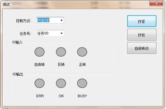
The control commands for tightening and loosening the electric screwdriver have two sources: "IO port" (electric screwdriver button) and "PC software."
If the command source is selected as "IO port," the external IO command is valid, and the "PC software" command is invalid;
If the command source is selected as "PC software," the external IO port command is invalid, and the "PC software" command is valid, only the following operations are valid.
Debug and execute the actual operation of each task, and make corresponding adjustments to the task based on the actual operation.
Long press the [Tighten] button to start tightening, lift your finger to stop tightening;
Long press the [Loosen] button to start loosening, lift your finger to stop loosening;
Long press the [Free Rotate] button to start free rotation, lift your finger to stop free rotation;
[Note: When switching the command source to PC software, please first confirm whether the three states of forward/reverse/free rotation of the IO port have been canceled; otherwise, the switch will not be successful.]
(6) Working Waveform
The tightening waveform is the full-state feedback of the tightening process; by analyzing the waveforms of position, speed, current, and torque, various problems that occur during the tightening process can be identified.
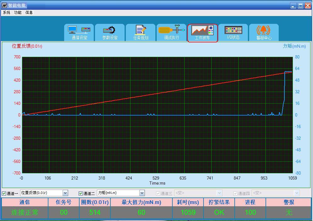
Display detailed waveform data of the entire process for each screw during locking, with a sampling accuracy of 3ms. Select a specific area to enlarge the waveform, right-click to return to the previous enlarged display state. When saving the waveform, you need to set the collection quantity in the system options, and then switch to the current waveform module; if not in this module, the waveform will not be collected and will not be saved.
(7) Input and Output Status
I/O displays the current controller input and output, working status, and alarm status; gray indicates no signal, green indicates signal present.
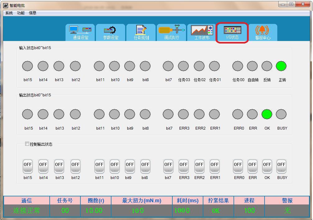
When the control output status is checked, IO signals can be forced to output.
(8) Alarm Center

Alarm information includes number, alarm name, and cause analysis, which can quickly locate the problem. The controller can save 10 alarm records, using a first-in, first-out method, removing the oldest alarm record.
Click "Clear Alarm" to clear all alarm records.
The alarm function selection can block or open certain alarms.
The specific alarm code table is as follows:
| Number
|
ERR0~3 Lights
|
Name
|
Alarm Cause
|
| 1 |
0000 |
Floating High |
Did not reach the specified lower stroke limit, reached the target torque; |
| 2 |
0001 |
Stripped Thread |
Reached the specified upper stroke limit, did not reach the target torque; |
| 3 |
0010 |
Overcurrent |
Short circuit in the motor line or power line, or large fluctuations in power supply voltage; |
| 4 |
0011 |
Overvoltage |
Power supply voltage exceeds the normal voltage range of the controller; |
| 5 |
0100 |
Undervoltage |
Power supply voltage is below the normal voltage range of the controller; |
| 6 |
0101 |
Flying Car |
When powered on, the bit is not in a free suspension state, with obstacles on both sides; or the target speed exceeds 1800rpm; or when saving task parameters, the bit is not in a free suspension state, with obstacles on both sides; |
| 7 |
0110 |
Electric Screwdriver Overheating |
Encountering obstacles during movement; or when powered on, the bit is not in a free suspension state, with obstacles on both sides; or when saving task parameters, the bit is not in a free suspension state, with obstacles on both sides; |
| 8 |
0111 |
Reverse Not in Place |
Encountering obstacles during reverse movement; encoder line not connected or poor contact. |
| 9 |
1000 |
Position Deviation Too Large |
Encountering obstacles during movement; or when powered on, the bit is not in a free suspension state, with obstacles on both sides; or when saving task parameters, the bit is not in a free suspension state, with obstacles on both sides; check if the encoder line is connected properly. |
| 10 |
1001 |
Electric Screwdriver Disconnection |
Electric Screwdriver Disconnection |
| 11 |
1010 |
Torque Deviation Too Large |
Screw does not match the bit; |
Note: When an alarm occurs, the ERR port will output an indication, and the specific alarm category can be found according to the output codes of ERR0~ERR3.
(9) Work Records
The work record module records the statistical data of the tightening system over a period of time.

Records the tightening process parameters and results for each screw. A maximum of 21,000 records can be kept, and after exceeding 21,000 records, the system will automatically maintain the deletion of records.
(1) Click [Query] to query all records; precise queries can be achieved by setting query conditions.
(2) [Clear Records] clears all existing records, emptying the records.
During the query, the statistical data shows three states: "OK," "NG," and "Incomplete"; the total count is the sum of the three.
(3) Scanning products that have been tightened will display the tightening results of the relevant screws and the corresponding photos and screw positions of the product.
(10) Waveform Comparison
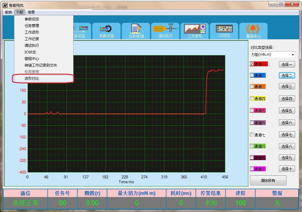
Up to ten waveforms can be selected for comparison, and the waveform types must be the same to compare the consistency of the tightening process.
(11) System Options
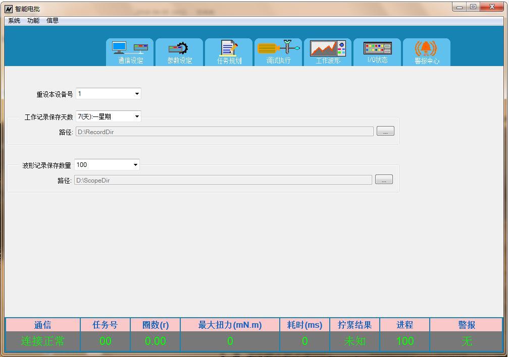
During the networking process of multiple controllers, different device numbers must be set for different controllers. When changing the device number, the software will automatically prompt whether to continue and indicate whether the modification of the device number was successful.
The saving time and path for work records can be set according to actual needs.
The number of waveform records saved and the save path can be set.
Note: Waveform records need to be switched to the waveform display page to generate waveform record files; the save path for waveform record files cannot be the same as the save path for work records to avoid accidental deletion of record files by the system during automatic file management.
(12) Permission Management
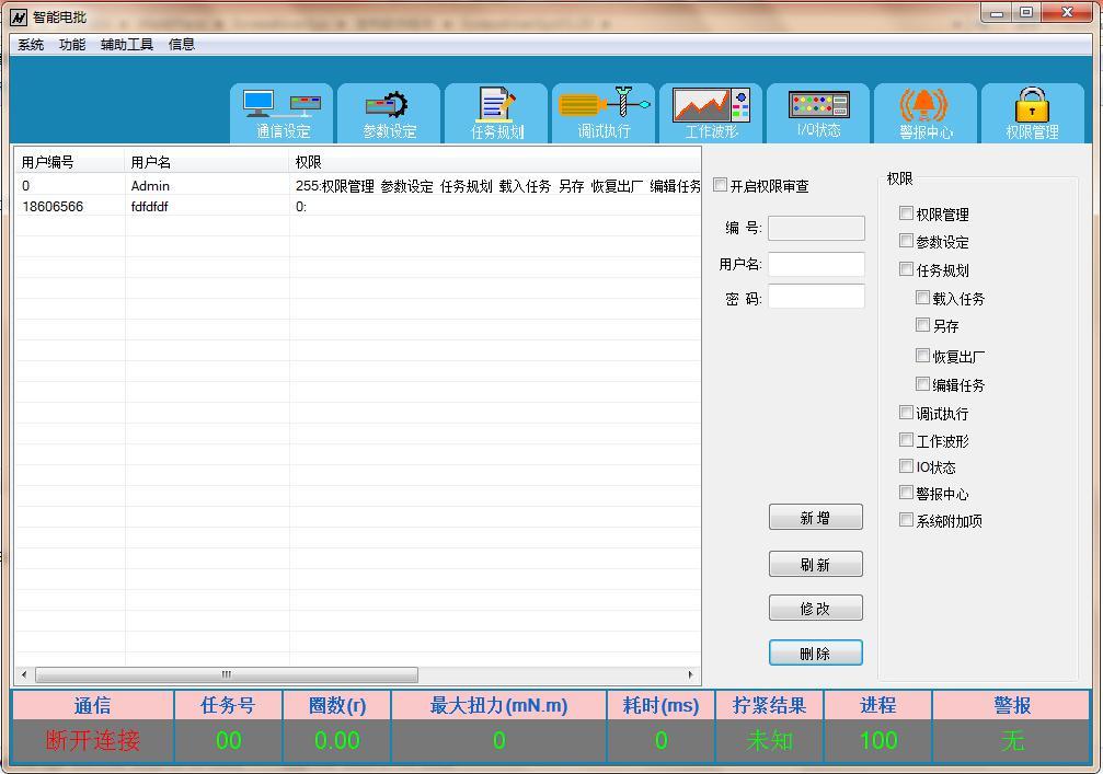
Manage user permissions, granting different permissions to different users.
(13) Product Workpiece Management
Management of adding, deleting, modifying, and querying product workpiece information; set the number of screws and image information for template types to facilitate workers in retrieving relevant product tightening requirements and process information.
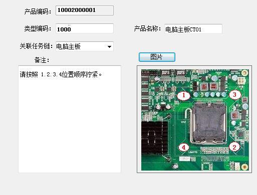
① Supports task chain technology, allowing different specifications of screws on the same workpiece to automatically and seamlessly switch tasks during the tightening process; it can be a single task operation or a multi-task serial operation.
② Supports management of adding, deleting, modifying, and querying product workpiece information;
③ Supports scanning for queries;
(14) Anti-leak Tightening Function
Uses infrared sensing technology, combined with software task chain for tightening process management. When removing a workpiece with an incomplete task chain, the system prompts an alarm.
Chapter 4 Hardware and Software Configuration List
| Serial Number |
Device Name |
Model |
Quantity |
Remarks |
| 01 |
Control Chassis |
DP-HS-001 |
1 unit |
Controller; Handheld Electric Screwdriver; Industrial Tablet Computer; |
| 02 |
Scanning Gun |
SCN-RS6601 |
1 piece |
Interface RS232 |
| 03 |
Infrared Sensor |
IR30M |
1 piece |
|
| 04 |
Management Software |
ScrewdriverSys V1.50 |
1 set |
Software + Database |
Note: Necessary cables are not listed one by one.
Chapter 5 Testing and Acceptance
1. Is the software communication connection normal after startup?
2. Are the software read/write parameters normal?
3. Is the forward/reverse rotation of the handheld electric screwdriver normal?
4. Is the tightening result prompt normal? Is the alarm for abnormalities normal?
5. Test the torque accuracy according to the standard; does the torque accuracy meet the requirements?
6. Are the controller input/output signals normal?
7. Are the tightening records saved successfully?
8. Is the management of adding, deleting, modifying, and querying workpieces normal?
9. Task chain testing, anti-leak testing;
Chapter 6 Warranty Regulations
This product has a warranty period of 1 year from the date of purchase (based on the shipping date); we provide free repairs for non-human quality issues within one year, and a nominal fee will be charged after one year.
During the warranty period, if any of the following situations occur, repair fees will be charged.
1. Cannot provide valid proof of purchase.
2. Damage caused by customer disassembly.
3. Damage caused by dropping.
4. Damage caused by collision during machine debugging.
5. Damage caused by not connecting the power supply according to the instructions.
Key words:
Links:

Website:www.sensewee.com
Contact: Lu Sheng Sales Engineer
Mobile:19928718048
Contact: Liu Sheng Sales Engineer
Mobile:15818689397
Contact: Gao Sheng Sales Engineer
Mobile:19925455058
Address: 608, Building G, Longjing Science Park, 335 Bulong Road, Bantian Street, Longgang District, Shenzhen City, Guangdong Province